2 wire temp sensor wiring diagram
It is important to get the wiring of your sensor correct otherwise the measuring. On Apr 11 2022.
1 Wire Or 2 Wire To Three Wire Coolant Temp Sensor Conversion Info Nasioc
Ad Free 2-day Shipping On Millions of Items.

. Single wire thermistor reads to ground. Ad Temperature Switches Sensors RTDs. 2 Wire Knock Sensor Wiring Diagram 2 Wire Knock Sensor Wiring Diagram.
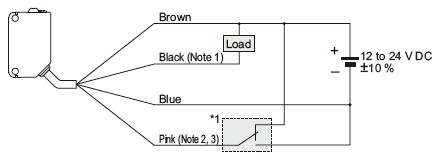
08-25-2015 0608 PM. 11 and 19 this one is important -. You must use a main relay that supplies both the injectors and your MegaSquirt controller as shown in the external wiring diagram above.
The camshaft position sensor consists of three wires. 2 wire temp sensors etc how to wire. In this illustration we will going to wire the DS18B20 single wire temperature sensor.
Post by Ignition Fri Jul 09 2010 936 pm. If youre wiring atemp sensor to an AVI you need to connect an external 5V pullup resister. 2 3 Wire Crank Sensor Wiring Diagram With Pictures Leave a Comment.
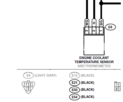
In the wiring diagrams below you will notice the different call outs for the Polarized vs. - Indication of Non-Polarized wiring. Coolant temperature sensor test axleaddict ect wiring diagram the owner of this car.
Vdo coolant temperature sender 120 c m14 sensors keyence america zeitronix installation single or. The wiring of a Pt100 temperature sensor is different to other temperature sensors in particular thermocouples. Air Intake Temperature Sensor.
2 Wire Temp Sensor Coolant Temperature Wiring Diagram. One for voltage and the other two wires are ground and signal wire the signal wire goes to the computer from the. Two wire sensors apply a voltage across sensor and read the voltage differential.
2 Wire Temp Sensor Wiring Diagram. A four-wired oxygen sensor has four wires two wires for the heater circuit and two. The knock sensor has two wires one for the signal and one for the ground.
When the crankshafts reluctor ring comes closer to the crank sensor. The 2 wire sensor in the. A two-wire crank sensor is usually an inductive type sensor which consists of a sensor magnet and coil.
A 4-wire oxygen sensor wiring diagram is also called a universal O2 sensor wiring diagram. The digital DS18B20 Sensor provide fairly good accuracy and range of connection. The color of the engine coolant temperature sensor varies and is color-coded.
On May 06 2022. 23 wires drive by wire stepper motors bi and unipolar ignition. The wiring diagram of the coolant temperature sensor is based on year make and model.
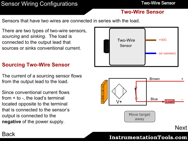
Two Wire Sensor Working Principle And Animation

Microsquirt Introduction
Rtd Wiring Diagrams

Which Wire Goes Where For The Cylinder Head Temp Sensor On To Hook Up To Megasquirt Pelican Parts Forums
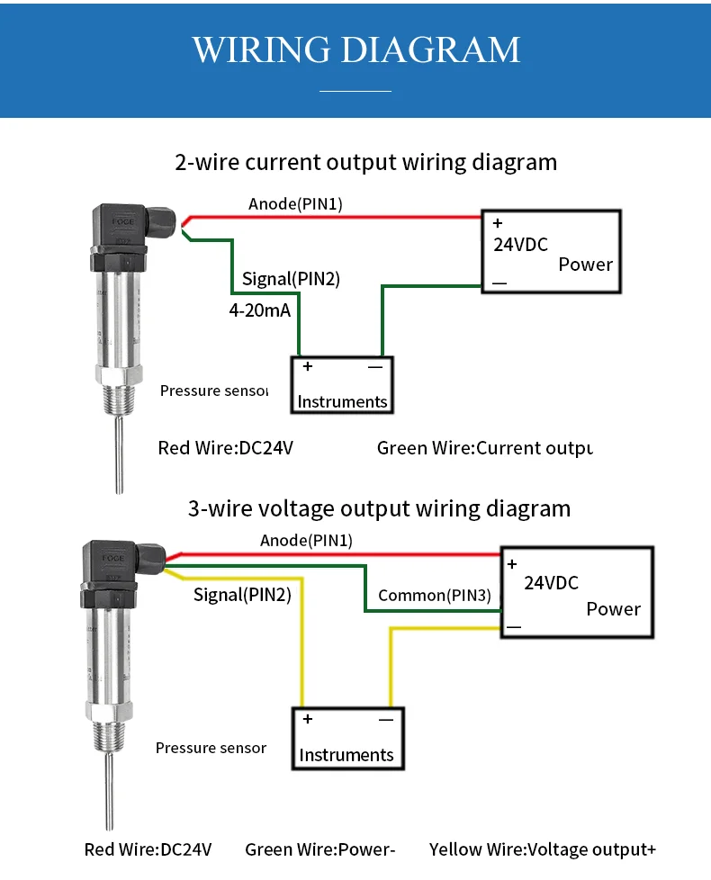
2 Wire 4 20ma Output Intelligent Pt100 Rtd Temperature Sensor Transmitter Buy 4 20ma Pt100 Temperature Transmitter Pt100 Rtd Temperature Sensor Head Mounted Temperature Transmitter Product On Alibaba Com
.jpg)
Inside A Car Coolant Temperature Sensors
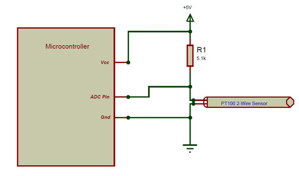
Pt100 Rtd Sensor Pinout Features Uses Guide Datasheet

Controlbyweb Temperature Sensor For Controlbyweb Products
Figure D 2 The Dissolved Oxygen Sensor Wiring Diagram Download Scientific Diagram
Zeitronix Installation Single Or Multiple Sensor Installation

Wilkerson Instrument Company Inc Blog Rtd Two Wire Transmitters And How They Work
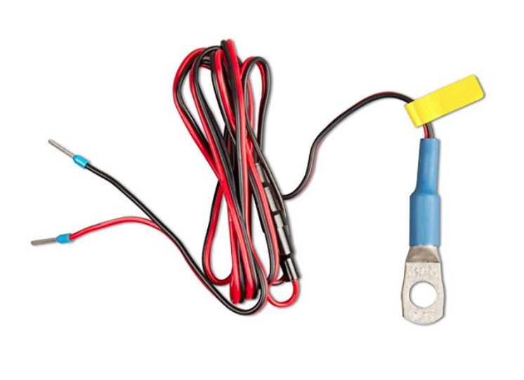
Help Wiring Up Temp Sensor And 2 Leads On Bmv 712 Victron Community

Coolant Temperature Sensor Wiring Diagram Awesome Sensor Wire National Electric

Pentair Temp Sensor 4 Wire Vs 2 Wire R Pools
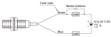
Cylindrical Inductive Proximity Sensor Gx U Gx Fu Gx N Discontinued Products I O Circuit And Wiring Diagrams Panasonic
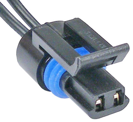
Gm 2 Wire Coolant Temperature Sensor Connector The Repair Connector Store
Compact Photoelectric Sensor Cx 400 Ver 2 I O Circuit And Wiring Diagrams Panasonic